Checking and Replacing the Flow Sensor
-
Safety Measures
Before starting maintenance, you must:
- Turn off the boiler power.
- Drain the water from the boiler.
-
Removing the Front Panel
To access the flow sensor, follow these steps:
- Detach the 4 clips of the boiler’s front panel (two at the top and two at the bottom).
- Carefully remove the front cover, avoiding cable disconnection.
- Disconnect the control display and grounding cable attached to the front panel.
- Secure the control display to the boiler casing with magnets.
-
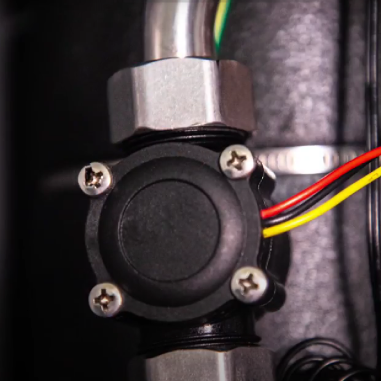
Locating the Flow Sensor
Watch the video to see what the flow sensor looks like. It is installed on a stainless steel tube located on the boiler tank.
-
Method 1 – Checking the Flow Sensor on a Test Bench
- Remove the flow sensor: the sensor has three wires: red, black, and yellow.
- Apply voltage: supply a constant 5-volt DC voltage between the red and black wires.
- Prepare the multimeter: set the multimeter to DC voltage measurement mode, calibrated for 20 volts.
- Connect the multimeter probes: connect one probe to the black wire and the other to the yellow wire.
- Check the static mode: in static mode, the indicators should show zero.
- Simulate water flow: create an airflow through the sensor by any convenient method.The indicators should show 1.5 – 2 volts.
If the measured value differs from the above, the sensor has failed and should be replaced.
-
Method 2 – Checking the Flow Sensor Directly on the Boiler
- Remove the flow sensor: unscrew two nuts to remove the sensor.
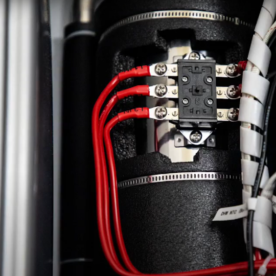
- Disconnect the pump power terminals: unplug the pump power connector or disconnect terminal W on the terminal block.
- Turn on the boiler power: observing safety measures, turn on the boiler’s electrical power.
- Access the boiler settings: activate parameter P1 in the settings to turn on the pump. Go to parameter P3 to measure the flow. 5. Simulate airflow: create an artificial airflow through the sensor. Observe the data on the screen for the simulated flow.
If the boiler display shows zero, the sensor is not working and should be replaced.
-
Replacing the Flow Sensor
- Remove the faulty sensor by unscrewing two nuts.
- Disconnect the sensor cable from the control board (WFS terminal).
- Install the new sensor by performing all actions in reverse order, following the direction indicated by the arrow on the sensor body.
-
Starting the Boiler
- Fill the boiler with the heat carrier.
- Perform the air removal procedure from the boiler using service parameters P1 and P3.
Instructions that will be useful to you
Previous
The next